[tagsList]
How to use this lab?
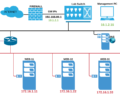
- IP addressing and network diagram are located at this URL – https://www.testclue.com/f5-lab-setup/
- Please read information provided on above page carefully.
- For support during lab hours, please use the live chat option at bottom right corner of lab page.
- There are two buttons on top of this page for quick access to lab diagram and to come back to lab console
- Once you are connected to mgmt PC and want to come back to lab console, use “Back to Lab Console” Button
- Users can choose to follow lab guide or perform configuration of their own.
- Only basic minimum config is done on lab devices, there is mgmt IP and default GW and license applied.
F5 LTM Initial Setup
- Login to Management PC, using credentials: labuser/Labroot12!@
- Login to F5 devices using browser in PC, F5-1 : https://192.168.80.2
- On Welcome page, under Setup Utility –> Click – Run the Setup Utility
- On General Properties Page – Observe licensed modules (do not click re-activate, this could result in invalidation of license and renewal process could take 3 working days)
- Click Next, On “Current Resource Allocation Page” – Observe the commissioned modules. Current appliances have CPU and Memory for LTM/DNS module, if you need APM/AFM modules, please contact support.
- On next page, it is possible to import the SSL certificate for appliance, this is useful for renewal of certificate, observe and click next
- On next page you will find mgmt. IP, mask and gateway settings along with hostname, host IP address and Time Zone. Change the time zone to your local time zone if not already set. Leave other settings as it is, you can also enable/disable root access to device from here. SSH IP Allow options lets administrator set the source IP from where device could be remotely accessed via SSH. At present, passwords are set to default, do not change the passwords. F5 default passwords : GUI – admin/admin, CLI – root/default
- Click Next
- Repeat similar steps for F5-2 : https://192.168.80.3
Standard Network Configuration
- On F5-1, Click Next to start configuring network, NTP, DNS and HA properties of the device.
- On Redundant Device Wizard Options: make sure both boxes are checked. Config Sync is used for keeping configuration similar on both members of HA pair. High Availability option selects failover method and mirroring option. There is special HA serial cable which can be purchased to connect two hardware appliances together, in this lab we will use only Network based HA.
- Click next and fill Internal Network Configuration as shown in screenshot below, information on addressing can be found on the lab diagram (accessible from “Diagram” Button in Upper Right Lab Area).
- 1.1 is connected to internal Vlan (towards backend servers).
- 1.2 is connected to external Vlan (in which Virtual IPs are created),
- 1.3 is reserved for HA purpose.
- You can set any random vlan number or leave it to “auto” as the traffic will be left untagged in this case. Click Next
11. Test the network connectivity:
- Go to command line on lab PC and ping: f5bigip1.testclue.local, and then f5bigip2.testclue.local.
- Try to ping IPs from from F5-1 bigip appliance to F5-2.
- Try to ping 10.1.2.1 from both F5 appliances CLI, this is default gateway for the external vlan.
- Try to ping 172.16.1.11, 22 and 33 from both F5 CLIs, these are pre-deployed backend servers.
- If all tests work OK, then your lab is setup properly and ready for advanced configuration.
- Go to “Network” tab on left-hand panel and check: Self IPs, VLANs. You will find the IPs and VLANs created earlier during configuration.
Creating Nodes
Click on “Local Traffic” on left-hand panel and click “Nodes”, add nodes as shown in screenshot below, the backend nodes are 172.16.1.11, 22 and 33. These backend servers are running on Linux and listening on ports 80 and 443.
Click Create, and add details as shown in next screenshot:
Click, Finished and in Nodes menu, click “Default Monitor” tab, next to “Node List” tab, and add ICMP as default monitor:
Click on Nodes again and observe if WEB-11 turns to green circle.
Repeat Similar Steps for WEB-22 and WEB-33 (refer to lab diagram), you will not need to create “Default Monitor” again as same monitor for WEB-11 can be used for other nodes.
Creating Pools
In Next step, we will create Pool, which will represent service pools, such as HTTP, HTTPS pools.
Click on Pools from left-hand panel, under Local Traffic and create pool as shown:
- Click Finished, you should see http-pool listed under pool list tab
- Click on Pools again from left-hand panel, the pool should appear green as all the nodes under pool are in good health.
For F5 exam, it is quite important to know the difference in states of nodes, pools, pool members, VIPs.
Secure NAT (SNAT) & Automap Configuration
SNAT is needed to make sure that traffic follows same route back and forth. If backend servers have default GW different than F5 appliance, then the return traffic from backend will go via different route, resulting in broken or asymmetric sessions.
We have created backend nodes and service pool, now we will build frontend using Virtual IPs. Before starting Virtual IP configuration we must create SNAT pool, this is the pool of IP addresses used by VIPs (Virtual IPs) to NAT the source IP of client coming from outside, this is done for assuring symmetric routing path. The traffic which comes through F5 appliance must go back via F5 appliance.
- Under Local Traffic tab, click on :
- Address Translation –> SNAT Pool List
- Click create, IP range 172.16.1.200 – 220 is reserved for SNAT pool.
- for configuration to work only 1 single IP will be fine, add 3 IPs to the SNAT pool:
- Click Finished.
Creating VIP
- Click on Virtual Servers, click Create and fill in details as below
- Use IPs from this range for creating a VIP : 10.1.2.200-220
- Next below on the VIP configuration page, select Default Pool as http-pool and click Finished.
- Notice the VIP status will be green as the pool behind the VIP is functioning properly.
- From browser window in Mgmt PC, open the link: http://10.1.2.200 refresh the page multiple times, and observe which backend server is displayed,
- The single VIP will be sending client requests to 3 different backend servers.
- The load-balancing method here is default Round Robin, this could be changed from Pool –> Members configuration. You may have to hit refresh or F5 multiple times to change the backend server.
- Testing can be done from internet as well using : http://proxy.testclue.com:3080 [this will work only for VIP created with IP 10.1.2.200]
- Next, is to create another pool for https service and VIP for frontend, you can try with different load-balancing methods under Pool config.
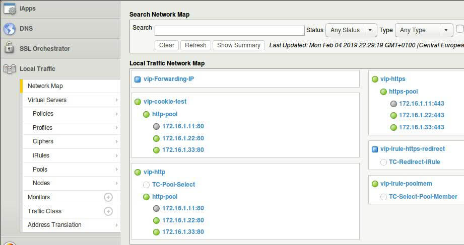
Using Network Map
The network map shows a summary of local traffic objects, as well as a visual map showing the relationships among the virtual servers, pools, and pool members on the BIG-IP® system.
It is also possible to search objects using search bar on top of page. Specially for larger configuration there can be multiple objects and in that case search comes handy.
- On the Main tab, click Local Traffic > Network Map .
- View the relationship of objects associated with each virtual server on the BIG-IP system.
- From the Status list, select a status.
- From the Type list, select an object type.
- Click the Show Summary button.
LTM Component Statistics
F5-BIGIP provides statistics for various Traffic components, it is possible to access all types of statistics from a single common page. Statistics page could be reached via multiple possible ways.
- Click on Local Traffic Tab
- Click on Pools –> Pool List and click on on http-pool –> Statistics
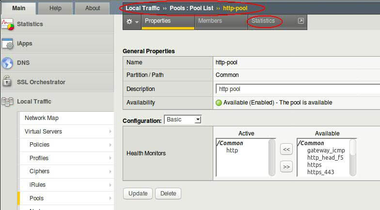
- Observe the traffic stats on different pool members, if you don’t see any figures, refresh webpage on VIP couple of times.
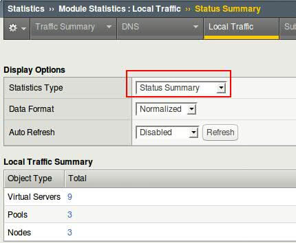
- Another way of reaching stats page is, from Statistics (tab on top) –> Module Statistics –> Local Traffic
- From Drop Down choose and observer Virtual server, Pools and Nodes statistics
- Select all pool members from pool and reset the statistics after observation.
Static Load Balancing Methods
Roundrobin, Ratio (members and nodes) are static load balancing methods which can be configured at pool level. Round-robin is the default method of load balancing.
Configuring Ratio(Member) Loadbalancing
In this method separate ratios or weights are assigned to each individual pool member and members with higher assigned weight gets more traffic.
- Browse to Local Traffic –> Pools –> Click on http-pool
- Change load balancing method from drop-down menu to Ratio Member and click update
- Refresh the VIP webpage few times, did you see some change? No, because we have not assigned any ratio values to pool members.
- Click on individual pool member and assign Ratios as shown in screenshot
DIY Task : Following above steps, try to configure Ratio(Node) loadbalancing. Remember, you will need to assign ratio directly to nodes and not members.
Dynamic Load Balancing Methods
Dynamic load balancing methods are based on working performance of pool members or nodes. BIG-IP decides which node/member to send traffic to based on following algorithms :
- Least Connections (node/member)
- Observed (node/member)
- Predictive (node/member)
- Dynamic Ratio (node/member)
- Weighted Least Connections (node/member)
- Ratio Least Connections (node/member)
- Fastest (node/application)
Assigning Priority Groups
Priority Group Activation (PGA) lets creation of priority groups within a pool. For example there are 4 pool members in a pool, and 2 of them are faster servers and other 2 are slower ones, thus it will be desirable to send traffic to more capable backend servers and have slower ones stand in as backup.
Configuration Tasks : We will create 2 priority groups within http-pool, one with value 5 and other with 2.
Configuration Tasks : We will create 2 priority groups within http-pool, one with value 5 and other with 2.
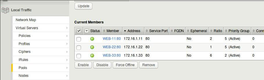
- Navigate to Local Traffic >> Pools >> http-pool >> Members
- Click on pool member WEB-11:80 and assign 5 as Priority Group value
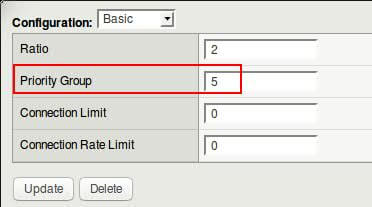
Repeat same steps for 2nd and 3rd members, and configure them as shown in screenshot below.
- Hit refresh on VIP webpage few times and observe which backend web server returns the page.
- Check pool member statistics to observe how traffic is distributed between pool members, remember to reset the counters after checking (not good idea in production environment though)
LTM Profiles
What profiles can do?
Configuring LTM Profiles
Persistence Profiles
Using OneConnect Profile
SSL Offloading Using Profile
- difference between client ssl profile and server ssl profile
- http pool can used to demonstrate ssl profile
Conditional Processing using iRules
- link to devcentral for iRules
- few of the triggerss for creating iRules
- use case scenarios of iRules
- configuring iRules
- using iRule Editor
- example iRule to redirect traffic to one specific member of pool
- example iRule to redirect traffic to one specific node
- example iRule to redirect http traffic to https VIP
Virtual Server Types
- different types of virtual servers available
- configuring forwarding virtual server for internal servers
BIGIP UCS Backups
For exporting / importing device configuration, UCS archive is used. You can create archive from existing config or upload config to a device.
- Click on System Tab
- Click Archives, and create a new archive with name – F5-lab–Device-1 (Repeat this on appliance 2, but with Device-2 in the end)
Loading UCS Archive on HA pair : In case you want to load UCS archive on HA pair after hardware failure, upgrade, replacement :
1. load ucs archive on active appliance
2. load ucs archive on standby appliance
3. sync the active appliance to device-ha-group
4. this will push loaded config from active unit to standby and bring both appliances in sync
5. screenshot explains the action needed to be taken
Configuring High Availability
Required parameters for HA:
- NTP – Both Devices must be synched and showing correct time.
- Port Open – Make sure that communication on F5 default ports is allowed between two appliances.
- Device Certs – devices must have ssl certificate installed on them.
- Click -> “Retrieve Device Information” after adding backup F5’s IP and admin/admin credentials
- Click -> Certificate Match button, verify the retrieved backup device name and click “Add Device”
- Wait for while, until screen refreshes and you see Peer device listed.
- On the peer/backup device, under Device Management -> Device Trust -> Device Trust Members you should be able to see active device listed automatically.
- Devices are in sync now, but setup is not completed as we must create Device Group.
- If backup device comes as active, please set it to standby by going to device properties and force it to standby by going to Device Management –> Devices and on the bottom of page by clicking “Force Standby”
- Now, on active F5 appliance, click on Device Groups, and create a new device group by following below screenshot.
- After clicking finish, it will take sometime until the devices adjust the sync, observe the top corner status on the GUI page.
- On, active device, click Device Management -> Overview and sync BIG-IP1 to the Device group created, this will push config from active device to all members of group (we have only 1 other member).
- For this lab, select Automatic with Incremental Sync, any new changes you will make will be auto synced to other device.
- Sync configuration manually : Click on Changes pending (top left of webpage, next to red F5 logo), and sync primary device to device group. This action must only be performed on Active/Primary unit, if executed on standby unit it results in loss of newly added config.
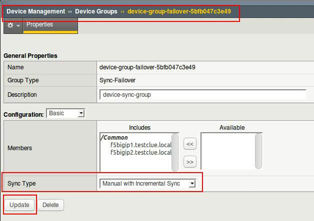
- Automatic / Incremental sync : On active unit – navigate to Device Management >> Device Groups >> device-group-failover-xxx and choose sync type from drop down and click update.
Note : Before establishing device trust, and especially if the designated BIG-IP is running different configuration (Virtual IPs, Policies, etc) from earlier, it is required to Force Offline the backup device. To do it, login to backup F5 device, click Device Management –> Devices, Scroll Down to Properties Tab and Set device to “Force Offline”. This is precautionary measure to not to overwrite the primary device once trust established.
Connection Mirroring & Failsafe
configuration of connection mirroring and failsafe vlan
Configuring iApps
iApp Configuration
Traffc Control Using Filters
packet filter to control traffic
Exploring F5 CLI
- directory structure
- modules – LTM, NET, SYS
- using tmsh
- commands and examples
Troubleshooting BIGIP – QKView and iHealth
- commands and examples
- uploading to iHealth.f5.com
BIGIP Status Indicators
- what different symbols mean?
- what different colors mean?
- combination of indicators at node, pool, member on vip
- adding monitors to components
Checking BIGIP Logs
- via GUI
- via CLI
Troubleshooting using TCPDUMP


Looking for something?
Upcoming Webinars
Tags
african virtual university
alignment
audio
Authentication
captions
cassandra
Cassandra Authentication
Codex
comments
content
css
database
database access control
distance learning
edge case
electrical engineering jobs
embeds
excerpt
F5 Lab Guide
featured image
formatting
gallery
html
image
indexing
lists
LTM Lab Guide
markup
mongodb
MongoDB Compaction
nsx
nsx controller
nsx manager
online education
online learning
post
Post Formats
read more
shortcode
standard
technical education
template
title
video
vmware